| Introduction |
| Physics of HTS |
| HTS materials |
| HTS leads |
| Resistive leads |
| Other activities |
| Contracts |
| Publications |
LHC Resistive leads
|
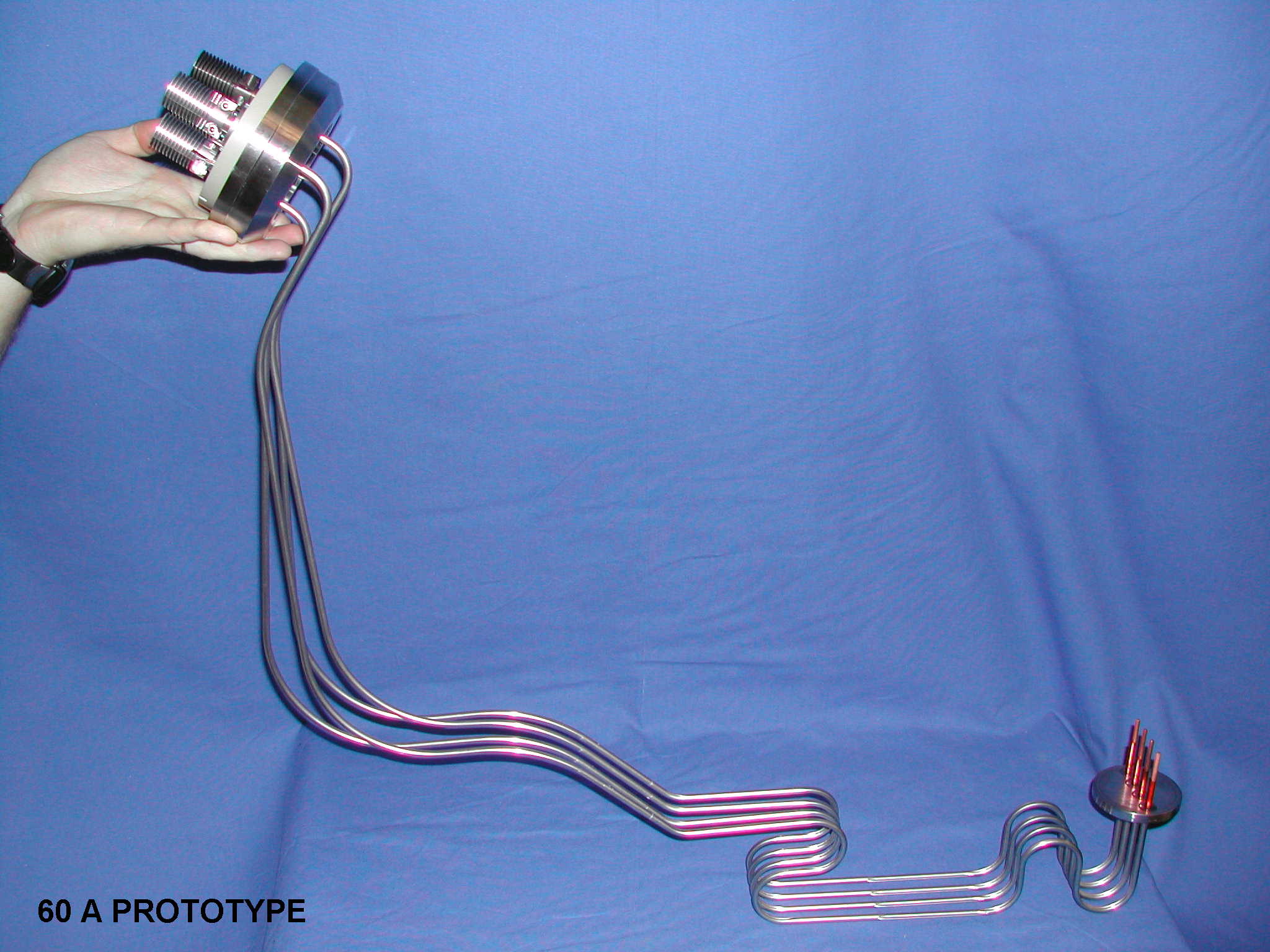
The powering of the LHC close orbit correctors will be made via 1504 current leads rated for a maximum current of 60 A. Additional 520 current leads are needed for the powering of the corrector magnets operating at currents of up to 120 A. At CERN, two different designs were developed for these leads: · a conduction-cooled design, for all the 60 A leads and for part -324 in total- of the 120 A leads; · a gas-cooled design for the remaining 120 A current leads.
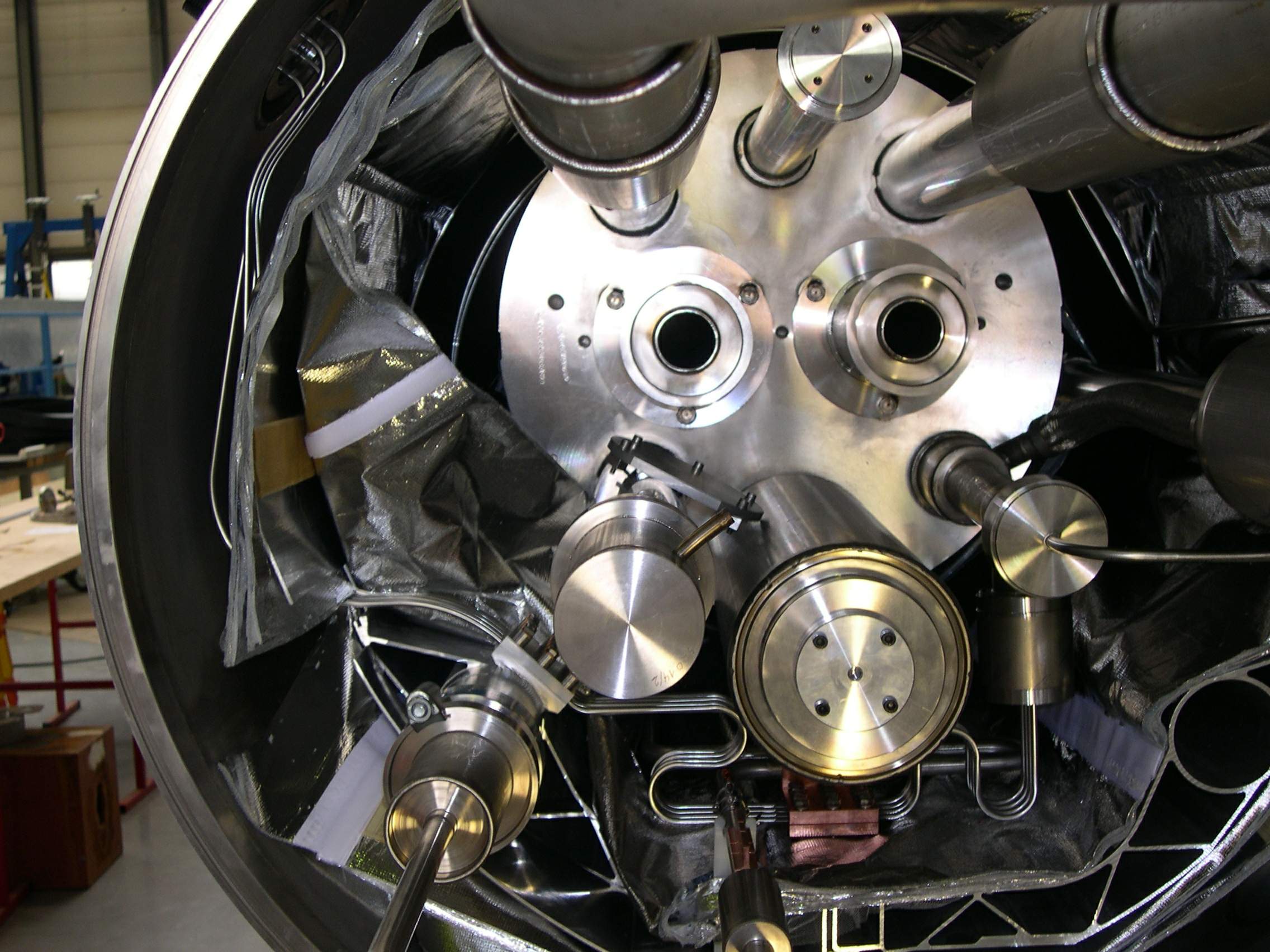
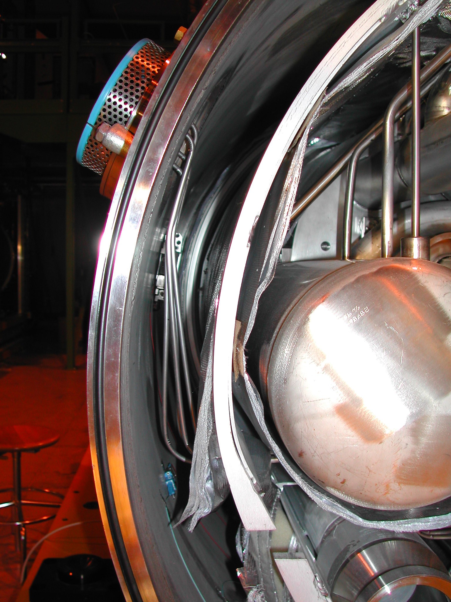
Conduction-cooled current leadsThe conduction-cooled current leads are integrated in the main vacuum insulation of the LHC Short Straight Section (SSS) cryostats. They transport the current from room temperature to the 1.9 K liquid helium bath. In view of their important number and of the strong space constraints imposed by the cryostat configuration, they are assembled in a group of four on a common stainless steel flange. They are pre-shaped as requested by the integration requirements, which require that these leads are the last components to be integrated into the already densely packed LHC cryostats. An hybrid conductor, electrical insulated via a multilayer Kapton® tube, is first inserted in a thin stainless steel tube and then pre-shaped with a tooling, specially developed at CERN. The four tubes are finally welded to the warm and cold stainless steel flanges. The hybrid conductor is a red brass rod that is copper plated along the entire length with two different copper thickness (thinner in the lower part). This hybrid conductor was chosen in order to minimize the heat load into the helium bath while assuring good stability in case of thermal run-away. The conductors of each assembly are thermalized against two heat sinks that are fixed to two cryogenic lines carrying gas at 50 K-75 K and at 5 K-20 K respectively. The heat sinking at intermediate temperatures is made in order to minimize the heat losses into the liquid helium bath. The design of these leads is extremely compact. It has the advantage, when compared to conventional self-cooled leads, of not requiring warm valves and pipes for the control and recovery of the helium flow. It avoids the use of cold vacuum-tight ceramic feedthroughs. In addition, thanks to the material choice and to the good design of the heat sinks, the leads have good thermal performance. The calculated losses into the helium bath of the a 60 A current leads are < 90 mW at 15 A, which is the average current estimated for these corrector magnets, and 170 mW at maximum current. For comparison, a conventional conduction-cooled current lead operating at 60 A would conduct about 2.5 W into the bath. The predicted thermal and electrical performance of the 60 A current leads have been confirmed by precise measurements performed on series components integrated in a ad-hoc cryostat built in the University of Southampton. The series production on the 60 A and 120 A conduction-cooled current leads is being manufactured on the basis of a CERN "build-to-print" design respectively in Mark&Wedell, Copenhagen, and in CECOM, Rome.
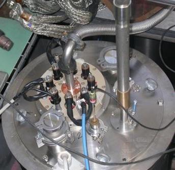
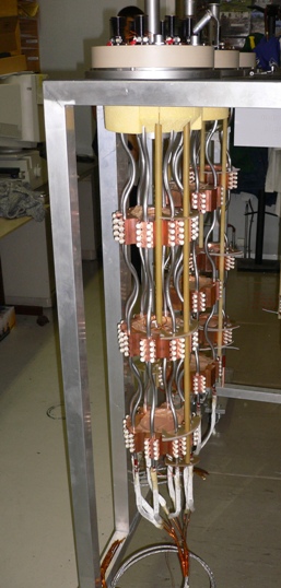
Gas-cooled current leadsThe gas-cooled current leads are integrated in cryostats, located in the insertion regions of the LHC machine, which house also the HTS current leads. They transport the current from room temperature to the 4.5 K liquid helium bath. The design is very compact. Depending on the requirements of the powering, the leads are assembled in groups of four or eight on a common supporting flange. The novelty of this design with respect to conventional self-cooled current leads consists in extracting the heat from the leads of the same assembly via common heat exchangers, cooled by the gas produced by the thermal conduction of the leads themselves at 4.5 K. This solution has two important advantages: the reduction in the number of valves needed for the cooling of the leads from one per lead to one per lead assembly, with significant economical savings in particular in view of the important number of leads, and the compactness of the design, which is made possible also by the simplification of the cooling scheme. The thermal performance of these leads is comparable to the one of conventional self-cooled current leads optimized for the same current rating.
|
gas-cooled current lead assembly (8 leads)
|
| last changed: 2005-11-23 | webmaster: Amalia Ballarino |